
|

|

|
Center for Space Radiations |
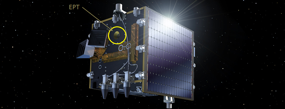
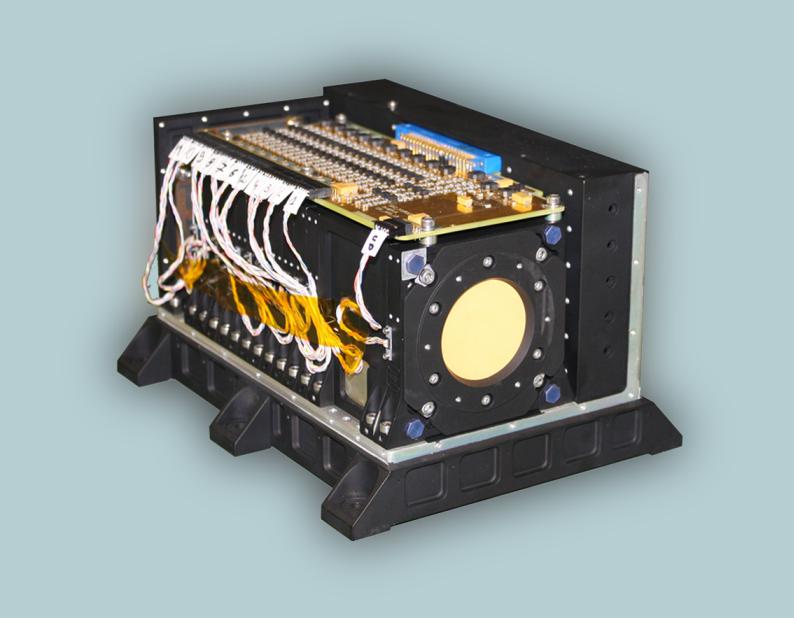
The EPT (Fig. 1) is a charged particle spectrometer comprising 23 Passivated Implanted Planar Silicon (PISP) detectors (~4.5 mm total thickness) mainly operating in digital mode to achieve direct particle identification and energy measurement. All the detectors have a thickness of 375 μm. A cross section view of the EPT is shown in Fig. 2, where twelve sensor modules can be clearly identified. The diameter of S1 is 3.5 mm and the outer diameter of S3 (surrounding S1) is 35 mm. S2 has a diameter of 20 mm. The front sensor modules, S1/S3 and S2 are separated by a 50 mm long serrated collimator that was designed to optimize the FOV angle definition. For most of the EPT operations, a sensor is considered as hit when it records at least 100 keV deposited energy. The S2 sensor serves as a trigger for all particle events recorded by the instrument.
The S1/S3 and S2 sensor setup constitutes the so-called Low Energy Section (LES) operated as a classical ΔE-E telescope for the detection of low energy particles. The analogue signals from these sensors are pre-processed by a Charge Sensitive Amplifier (CSA) and a Pulse Shaping Amplifier (PSA), then digitized at 20⋅106 samples per second using a 12-bit Analog-to-Digital Converter (ADC) and their pulse height is extracted and recorded by a dedicated firmware stored in a Field Programmable Gate Array (FPGA). Nine deposited energy intervals are defined for S2 (E sensor) and for each of these, four deposited energy intervals are defined in S1/S3 sensors enabling identification of electrons, protons, He-ions and any heavier ions (Z>2) respectively. The S1/S3 and S2 sensors also define the 52° FOV angle for protons (E<13 MeV) since any particle has to hit both sensors in order to trigger the classification process.
The High Energy Section (HES) comprises the S1/S3, S2 sensor and the stack of so-called Digital and Absorber Modules (DAM). Each DAM is made of a central 35 mm diameter sensor (Fig. 2) surrounded by an anticoincidence ring (AC) of 10 mm width; an energy degrader material (tungsten or aluminum) is accommodated in front of the central sensor. In order to perform the identification of incident particles along with energy channel determination, the energy deposited in S1/S3 and S2 as well as the bit pattern generated by hit DAMs are used. In principle, the energy deposited in S2 would be sufficient for particle identification, but in order to provide full contamination-free spectra, a particle is recorded by the EPT HES only if its identification by S2 is confirmed by S1/S3. Each of the 10 possible uninterrupted series of hit DAMs defines a HES channel (When registering the last DAM hit, all the preceding DAMs need also to be hit, while there is not a single AC detector hit). For particles detected by the HES, the field of view angle decreases with increasing number of hit DAMs, down to 24° for protons (E>248 MeV) hitting up to the last DAM. Electrons are only effectively detected up to DAM2 (<10 MeV).
The front window of the EPT is composed of a 200 μm aluminum foil, which in addition to the S1/S3 thickness, sets the lower limits of incident energies to 0.5 MeV, 9.5 MeV and 38 MeV, for electrons, protons and He-ions, respectively. The upper limits of incident particle energies are then defined by the number of DAMs and their corresponding absorber characteristics (thickness and material).
The energy channels defined for the PROBA-V/EPT mission are summurized in the table below.
| VC | Electrons | Protons | Helium |
|
0 1 2 3 4 5 6 7 8 9 |
0.5 - 0.6 0.6 - 0.7 0.7 - 0.8 0.8 - 1.0 1.0 - 2.4 2.4 - 8.0 |
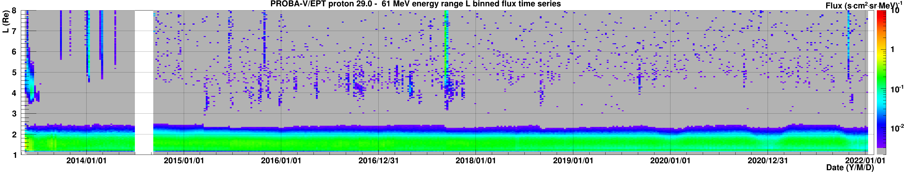
9.5 - 13 13 - 29 29 - 61 61 - 92 92 - 126 126 - 155 155 - 182 182 - 205 205 - 227 227 - 248 |
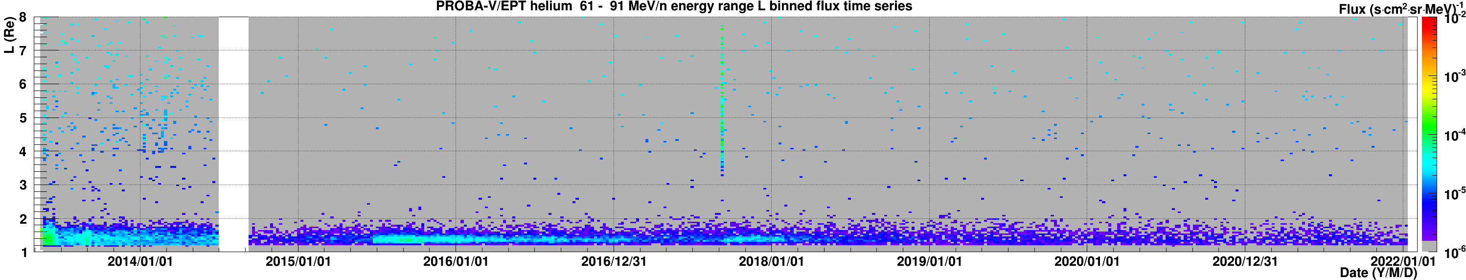
38 - 51 51 - 116 116 - 245 245 - 365 365 - 500 500 - 615 615 - 720 720 - 815 815 - 900 900 - 980 |
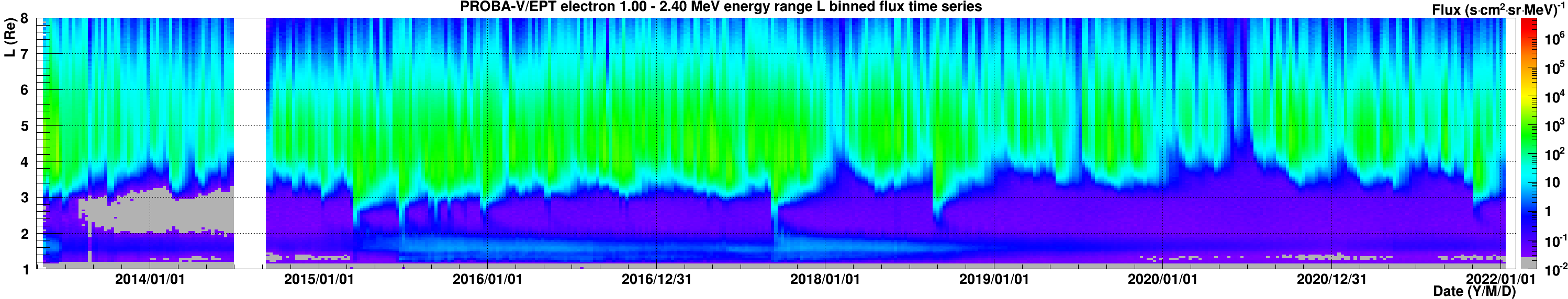
The EPT instrument with this channel configuration was installed onboard PROBA-V satellite that was launched on the 7th May 2013 onto a sun-synchronous circular Low Earth Orbit at 820 km altitude and 98.7° inclination. Its local time at descending node is 10:30 - 11:30. The EPT has been accommodated onto the PROBA-V satellite so as to get its boresight oriented Eastwards during local night time and Westwards during local day time at approximately 90° with respect to the local magnetic field. However, the East/West orientation has been modified by telecommands during the commissioning phase in 2013 and in 2017 to allow measurements of pitch angle distribution (PAD) of protons in some locations in South Atlantic Anomaly. Also due to specifity of the satellite operations the EPT orientation in in the southern hemisphere is systematically and strongly deviated from 90° with respect to local magnetic field during winters since 2019/2020. It automatically enriches the intentional PAD sampling performed in earlier years. Fig. 3 here below few examples of electron, proton and helium measurements performed by the PROBA-V/EPT are shown.
The numerical PROBA-V/EPT data time series as measured, and many other derived data products can be accessed via ESA Space Weather Network
Relevant publications of the CSR team using the PROBA-V/EPT data can be found here
Content reviewed on 2022/06/02